Disk Management in Operating System
Disk management is a crucial function of an operating system that deals with the efficient use of secondary storage devices such as hard disks and solid-state drives. The operating system is responsible for organizing disk space, managing free blocks, and ensuring fast and reliable access to stored data.
Since multiple processes may request disk access at the same time, the operating system must handle disk operations carefully to minimize access time and maximize system performance. Proper disk management also helps prevent data loss and improves overall system reliability.
Major responsibilities of disk management include disk initialization, free space management, disk scheduling, and error handling. These tasks ensure that the storage device operates efficiently under heavy workload conditions.
Functions of Disk Management
- Tracking free and allocated disk blocks
- Allocating disk space to files
- Managing disk access requests
- Handling disk errors and recovery
- Optimizing disk performance
Disk Structure and Components
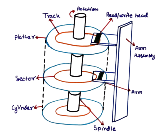
The diagram illustrates the internal structure of a magnetic disk used in an operating system for secondary storage. A disk consists of multiple circular disks called platters, which are stacked vertically and rotate together at high speed. These platters are coated with magnetic material and are responsible for storing data.
Each platter is divided into concentric circular rings known as tracks. Tracks are further divided into smaller units called sectors, which are the smallest addressable units on the disk. Data is always read from or written to the disk in terms of sectors. A set of tracks at the same position on all platters forms a cylinder.
At the center of the platters is the spindle, which rotates all platters simultaneously. The rotational movement allows the disk surface to pass under the read/write head. The speed of this rotation directly affects data access time.
The read/write head is responsible for accessing data from the disk. Each platter surface has its own head, and all heads are mounted on a common arm assembly. The arm moves horizontally across the platters to position the heads over the required track.
The movement of the arm assembly determines the seek time, while the rotation of the platter determines the rotational latency. Together, these factors influence how quickly data can be accessed from the disk.
This disk structure is the foundation for disk management and disk scheduling algorithms in an operating system, as the OS must efficiently decide how and when the read/write head moves to minimize access time and improve overall system performance.
Disk Scheduling Algorithms in Operating System
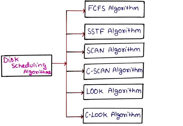
Disk scheduling algorithms decide the order in which disk access requests are processed. Since disk access time is much slower than memory access time, selecting an efficient scheduling algorithm is essential to reduce seek time and improve system throughput.
When multiple processes generate I/O requests, the disk scheduler arranges these requests in a specific order to minimize the movement of the disk head. Different algorithms are used depending on system requirements and workload patterns.
Objectives of Disk Scheduling
Disk scheduling is an important function of an operating system that decides the order in which disk I/O requests are serviced. Since disk access is much slower compared to main memory access, an efficient disk scheduling strategy is required to reduce delays and improve system efficiency. The primary objectives of disk scheduling are explained below in detail.
-
Minimize Disk Head Movement:
Disk access time largely depends on how far the read/write head has to move across the disk surface. Disk scheduling algorithms aim to reduce unnecessary head movements by servicing requests in an optimized sequence. Less head movement results in faster data access and reduced mechanical wear of disk components. -
Reduce Average Seek Time:
Seek time is the time required for the disk arm to move the read/write head to the desired track. By carefully selecting the next request to serve, disk scheduling algorithms reduce the average seek time for all I/O operations, leading to quicker response for processes. -
Increase Disk Throughput:
Disk throughput refers to the number of disk requests completed per unit time. Efficient scheduling ensures that more read/write requests are handled in a shorter period, making better use of disk resources and improving overall system productivity. -
Ensure Fairness Among Processes:
A good disk scheduling algorithm ensures that all processes get a fair chance to access the disk. It prevents situations where some requests are continuously delayed or starved while others are repeatedly served, maintaining balance in multi-user and multi-process environments. -
Improve Overall System Performance:
By minimizing delays, reducing seek time, and increasing throughput, disk scheduling directly contributes to better system performance. Faster disk access improves application response time, enhances multitasking efficiency, and provides a smoother user experience.
Important Terms Related to Disk Scheduling
To understand disk scheduling algorithms clearly, it is essential to know the key terms associated with disk operations. These terms describe how data is accessed from the disk and how scheduling decisions affect performance.
-
Seek Time:
Seek time is the time required for the disk arm to move the read/write head from its current position to the desired track on the disk. It is the most significant component of disk access time and directly impacts system performance. Disk scheduling algorithms mainly focus on minimizing seek time. -
Rotational Latency:
Rotational latency is the time taken for the disk platter to rotate so that the required sector comes under the read/write head. Even after reaching the correct track, the system must wait for the correct sector, making rotational delay unavoidable in traditional hard disks. -
Transfer Time:
Transfer time refers to the time taken to actually read or write data once the head is positioned over the correct sector. It depends on the disk’s rotation speed and the amount of data being transferred. -
Disk Access Time:
Disk access time is the total time required to access data from the disk. It is the sum of seek time, rotational latency, and transfer time. Efficient disk scheduling helps reduce overall disk access time. -
Disk Bandwidth:
Disk bandwidth is the total amount of data transferred by the disk per unit time. Higher disk bandwidth indicates better disk utilization and improved system performance. -
Disk Request Queue:
The disk request queue stores pending I/O requests waiting to be serviced. Disk scheduling algorithms decide the order in which these requests are processed to minimize delay and improve efficiency. -
Head Movement:
Head movement refers to the distance traveled by the disk head while servicing requests. Excessive head movement increases seek time and reduces disk efficiency, which is why scheduling algorithms aim to reduce it. -
Track:
A track is a circular path on the surface of a disk platter where data is stored. Each platter contains multiple tracks, and the read/write head must move between tracks to access data. -
Sector:
A sector is a subdivision of a track and represents the smallest unit of data that can be read or written on a disk. Each track is divided into several sectors. -
Cylinder:
A cylinder is a set of tracks located at the same position across all disk platters. Accessing data within the same cylinder is faster because it does not require additional head movement. -
Starvation:
Starvation occurs when a disk request is repeatedly delayed and never served because other requests keep getting higher priority. Some disk scheduling algorithms are designed to avoid starvation and ensure fairness.
1. First Come First Serve (FCFS)
FCFS is the simplest disk scheduling algorithm. Requests are processed in the order they arrive in the disk queue. There is no reordering of requests.
Although FCFS is easy to implement and ensures fairness, it may lead to excessive disk head movement and poor performance when requests are widely scattered.
FCFS (First Come First Serve) is the simplest disk scheduling algorithm. In this method, disk I/O requests are served strictly in the order in which they arrive in the request queue. There is no reordering or optimization of requests, making FCFS easy to understand and implement.
Given Example
A disk contains 200 tracks numbered from 0 to 199. The disk request queue is:
82, 170, 43, 140, 24, 16, 190
The current position of the disk head is at track 50. Using the FCFS algorithm, we must calculate the total seek time.
How FCFS Works in This Case
According to FCFS, the disk head will move in the exact sequence in which requests appear in the queue:
50 → 82 → 170 → 43 → 140 → 24 → 16 → 190
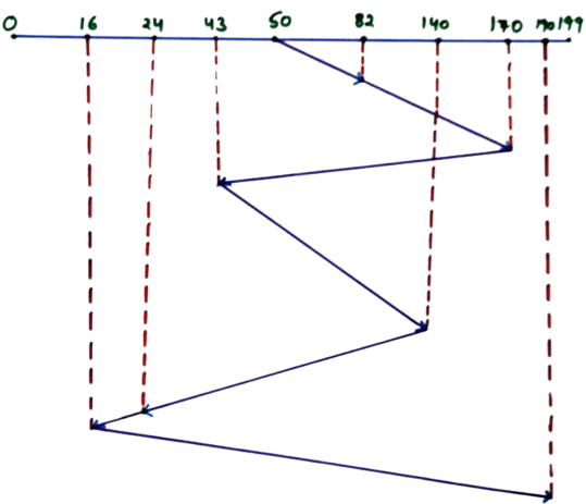
The diagram clearly shows this zig-zag movement of the disk head. Because FCFS does not consider the nearest request, the head travels back and forth across the disk surface, increasing total head movement.
Step-by-Step Seek Time Calculation
- |82 − 50| = 32
- |170 − 82| = 88
- |43 − 170| = 127
- |140 − 43| = 97
- |24 − 140| = 116
- |16 − 24| = 8
- |190 − 16| = 174
Total Seek Time
Total Seek Time = 32 + 88 + 127 + 97 + 116 + 8 + 174 = 642 tracks
Explanation of Result
The total seek time is quite high because FCFS does not optimize head movement. The disk head repeatedly moves long distances between requests, which increases seek time and reduces performance.
This example clearly demonstrates why FCFS is simple but inefficient for systems with heavy disk I/O operations. More advanced algorithms like SSTF, SCAN, or C-SCAN are preferred in real-world operating systems.
2. Shortest Seek Time First (SSTF)
SSTF selects the disk request that is closest to the current head position. By minimizing seek distance for each operation, SSTF significantly reduces average seek time.
However, SSTF may cause starvation, where requests far from the current head position wait for a long time.
SSTF (Shortest Seek Time First) is an improved disk scheduling algorithm compared to FCFS. In this method, the disk controller always selects the request that is closest to the current position of the disk head. The main goal of SSTF is to minimize the seek time by reducing unnecessary disk head movement.
Given Example
A disk contains 200 tracks numbered from 0 to 199. The disk request queue is:
82, 170, 43, 140, 24, 16, 190
The initial position of the disk head is track 50. We must calculate the total seek time using the SSTF algorithm.
How SSTF Works in This Case
At every step, the disk head moves to the request that is at the shortest distance from its current position. Let us calculate the movement step by step.
Step-by-Step Disk Head Movement
-
Current head at 50
Nearest request: 43 (distance = 7) -
Head moves to 43
Nearest request: 24 (distance = 19) -
Head moves to 24
Nearest request: 16 (distance = 8) -
Head moves to 16
Nearest request: 82 (distance = 66) -
Head moves to 82
Nearest request: 140 (distance = 58) -
Head moves to 140
Nearest request: 170 (distance = 30) -
Head moves to 170
Nearest request: 190 (distance = 20)
Disk Head Movement Order
50 → 43 → 24 → 16 → 82 → 140 → 170 → 190
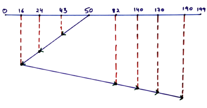
Seek Time Calculation
- |50 − 43| = 7
- |43 − 24| = 19
- |24 − 16| = 8
- |82 − 16| = 66
- |140 − 82| = 58
- |170 − 140| = 30
- |190 − 170| = 20
Total Seek Time
Total Seek Time = 7 + 19 + 8 + 66 + 58 + 30 + 20 = 208 tracks
Explanation of Result
Compared to FCFS, SSTF significantly reduces total seek time by always choosing the closest request. This minimizes disk head movement and improves overall disk performance.
However, SSTF may cause starvation, where requests far from the current head position may wait for a long time if closer requests keep arriving. Despite this drawback, SSTF performs much better than FCFS in most cases.
This example clearly shows how SSTF optimizes disk access by intelligently selecting the nearest request at each step.
3. SCAN Algorithm
The SCAN algorithm moves the disk head in one direction, servicing requests until it reaches the end, then reverses direction. It works similar to an elevator moving up and down.
SCAN provides better performance and fairness compared to FCFS and SSTF, especially under heavy loads.
SCAN disk scheduling algorithm is also known as the Elevator Algorithm. In this method, the disk head moves in one fixed direction and services all the requests coming in its path. When it reaches the last track in that direction, it reverses its direction and continues servicing remaining requests.
SCAN reduces unnecessary back-and-forth movement of the disk head and provides better performance than FCFS and SSTF in most practical systems.
Given Example
A disk contains 200 tracks numbered from 0 to 199. The disk request queue is:
82, 170, 43, 140, 24, 16, 190
Initial position of disk head = 50
Assume the disk head is initially moving toward the higher-numbered tracks.
How SCAN Works in This Case
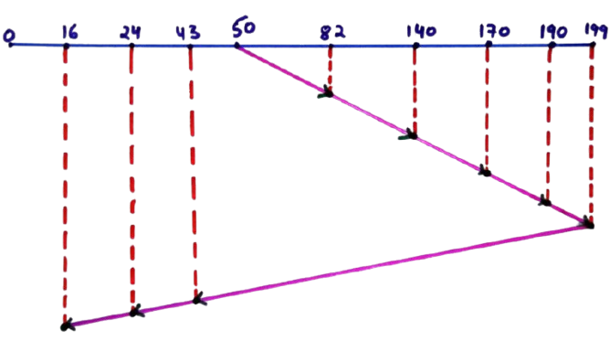
The disk head will move from track 50 toward the right end (199), servicing all requests that lie in that direction. After reaching the end, it reverses direction and services the remaining requests on the left side.
Disk Head Movement Order
Requests greater than 50 (served while moving right): 82, 140, 170, 190
Requests less than 50 (served after reversing direction): 43, 24, 16
Complete movement sequence:
50 → 82 → 140 → 170 → 190 → 199 → 43 → 24 → 16
Step-by-Step Seek Time Calculation
- |82 − 50| = 32
- |140 − 82| = 58
- |170 − 140| = 30
- |190 − 170| = 20
- |199 − 190| = 9
- |199 − 43| = 156
- |43 − 24| = 19
- |24 − 16| = 8
Total Seek Time
Total Seek Time = 32 + 58 + 30 + 20 + 9 + 156 + 19 + 8 = 332 tracks
Explanation of Result
The SCAN algorithm significantly reduces random disk head movement compared to FCFS. Unlike SSTF, it avoids starvation by ensuring that all requests are eventually serviced as the head moves in both directions.
Although the seek time is slightly higher than SSTF in this example, SCAN provides better fairness and predictable performance, making it widely used in real operating systems.
This example clearly shows how SCAN balances efficiency and fairness by moving the disk head systematically across the disk surface.
4. C-SCAN (Circular SCAN)
C-SCAN improves upon SCAN by servicing requests in only one direction. After reaching the end, the disk head returns to the beginning without servicing requests on the return path.
This approach provides uniform waiting time and is suitable for systems with high disk usage.
C-SCAN (Circular SCAN) is an improved version of the SCAN disk scheduling algorithm. Unlike SCAN, where the disk head services requests in both directions, C-SCAN services requests in only one direction. After reaching the last track in that direction, the head quickly returns to the beginning without servicing any requests during the return.
This approach provides more uniform waiting time for all disk requests and avoids the problem where requests near the middle get serviced more frequently than those near the ends.
Given Example
A disk contains 200 tracks numbered from 0 to 199. The disk request queue is:
82, 170, 43, 140, 24, 16, 190
Initial disk head position = 50
Assume the head is moving toward the higher-numbered tracks.
How C-SCAN Works in This Case
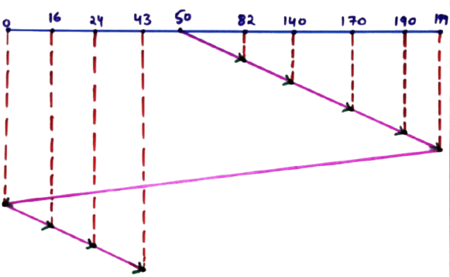
The disk head moves only in the right direction and services all requests greater than 50. After reaching the last track (199), it jumps directly to the beginning (track 0) without servicing any requests during this return movement.
Disk Head Movement Order
Requests serviced while moving right: 82, 140, 170, 190
Requests serviced after circular jump: 16, 24, 43
Complete movement sequence:
50 → 82 → 140 → 170 → 190 → 199 → 0 → 16 → 24 → 43
Step-by-Step Seek Time Calculation
- |82 − 50| = 32
- |140 − 82| = 58
- |170 − 140| = 30
- |190 − 170| = 20
- |199 − 190| = 9
- |199 − 0| = 199
- |16 − 0| = 16
- |24 − 16| = 8
- |43 − 24| = 19
Total Seek Time
Total Seek Time = 32 + 58 + 30 + 20 + 9 + 199 + 16 + 8 + 19 = 391 tracks
Why C-SCAN Is Used
C-SCAN treats the disk like a circular list, providing equal opportunity to all requests regardless of their position. Requests near the beginning of the disk do not have to wait for the head to scan back from the end while servicing others.
Although the total seek time may be higher than SCAN in some cases, C-SCAN offers better fairness and predictable response time, which is crucial for time-sharing and multi-user operating systems.
This example clearly demonstrates how C-SCAN ensures uniform disk access by allowing the disk head to move in a single, consistent direction.
5. LOOK Algorithm
LOOK is an optimized version of SCAN. Instead of going to the physical end of the disk, the head reverses direction after servicing the last request in that direction.
This reduces unnecessary head movement and improves performance.
LOOK Disk Scheduling algorithm is an improved version of the SCAN (Elevator) algorithm. In LOOK, the disk head moves in one direction and services all the requests in that direction only up to the last requested track, instead of going to the physical end of the disk.
Given Diagram Explanation
In the given diagram, the disk has track numbers ranging from 0 to 199. The request queue contains the following track requests:
16, 24, 43, 82, 140, 170, 190
Initial head position = 50
Direction of movement = Towards larger track numbers
Step 1: Split Requests Based on Head Position
Requests greater than 50:
82, 140, 170, 190
Requests smaller than 50:
43, 24, 16
Step 2: Head Movement Order (As Shown in Diagram)
The disk head first moves towards the right (higher track numbers) and services all higher requests in ascending order. After reaching the last request (190), the head reverses direction and services the remaining lower requests.
Head movement sequence:
50 → 82 → 140 → 170 → 190 → 43 → 24 → 16
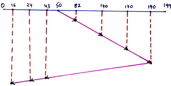
This zig-zag movement shown in the diagram represents how the head changes direction after servicing the highest requested track instead of going till track 199.
Step 3: Seek Time Calculation
- |82 − 50| = 32
- |140 − 82| = 58
- |170 − 140| = 30
- |190 − 170| = 20
- |190 − 43| = 147
- |43 − 24| = 19
- |24 − 16| = 8
Total Seek Time
Total Seek Time = 32 + 58 + 30 + 20 + 147 + 19 + 8 = 314 tracks
Key Observations from the Diagram
- The disk head does not go till the end of disk (199).
- Head reverses direction after the last requested track (190).
- This reduces unnecessary head movement compared to SCAN.
- LOOK provides better performance and lower seek time.
Conclusion
From the diagram-based example, it is clear that the LOOK disk scheduling algorithm optimizes disk performance by eliminating wasted head movement. It services requests efficiently while maintaining fairness among processes, making it a practical and widely used disk scheduling technique in operating systems.
6. C-LOOK Algorithm
C-LOOK (Circular LOOK) disk scheduling algorithm is a modified version of the LOOK algorithm. In C-LOOK, the disk head moves in only one direction. After servicing the last request in that direction, the head jumps back to the first request at the opposite end without servicing any requests during the return.
Given Example Details
Disk tracks range from 0 to 199.
Request queue: 16, 24, 43, 82, 140, 170, 190
Initial head position = 50
Direction of head movement = Towards larger track numbers
Step 1: Categorize Requests
Requests greater than head position (50):
82, 140, 170, 190
Requests smaller than head position (50):
43, 24, 16
Step 2: Head Movement Order (C-LOOK)
The disk head moves only in the forward direction. After reaching the highest requested track, it jumps back to the lowest requested track and continues servicing.
Head movement sequence:
50 → 82 → 140 → 170 → 190 → 16 → 24 → 43
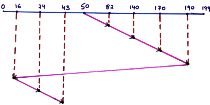
Note: The jump from 190 to 16 is a logical jump and no intermediate tracks are serviced during this movement.
Step 3: Seek Time Calculation
- |82 − 50| = 32
- |140 − 82| = 58
- |170 − 140| = 30
- |190 − 170| = 20
- |190 − 16| = 174
- |24 − 16| = 8
- |43 − 24| = 19
Total Seek Time
Total Seek Time = 32 + 58 + 30 + 20 + 174 + 8 + 19 = 341 tracks
Key Features of C-LOOK Algorithm
- Disk head moves in a single direction only.
- Eliminates back-and-forth movement.
- Provides uniform waiting time for all requests.
- More efficient than SCAN and LOOK in many cases.
Conclusion
From this example, C-LOOK shows how circular movement of the disk head reduces direction changes and ensures fairness. Although the jump adds seek distance, the algorithm offers predictable and efficient disk scheduling, making it suitable for systems with heavy disk I/O.
Comparison of Disk Scheduling Algorithms
| Algorithm | Seek Time | Starvation | Performance |
|---|---|---|---|
| FCFS | High | No | Low |
| SSTF | Low | Yes | Good |
| SCAN | Medium | No | Better |
| C-SCAN | Medium | No | Very Good |
| LOOK | Low | No | Excellent |
Conclusion
Disk management and disk scheduling play a vital role in operating system performance. By selecting appropriate scheduling algorithms, an operating system can significantly reduce disk access time and improve user experience. Modern systems often use optimized variants like C-SCAN and LOOK for better efficiency.